
Lithium Swap 7 - Contact
With the new cells strapped into a pack and installed in the car, properly secured, there was still some work to do. Holes were punched in the wall of the battery compartment and the floor of the car near the tail panel so that conduits for AC power and telemetry could be run properly. I had to put the driver's seat back in and run 12 volts and ignition (key on) to the BMS so that it would operate, as well as connect a loud buzzer under the dash for the BMS to annunciate any over or under cell voltages. The digital E-meter was brought out of storage and installed in its proper place in the console. I took a peek inside the controller cabinet and noted some crumbling high power resistors that would need attention eventually, but measurements of their values showed that they were still electrically correct.
Beneath the hood, I installed a big 100 ampere-hour Werker gel cell battery to run the car's 12 volt systems, providing a disconnect switch so that the system could be powered down if needed. There wasn't really a good reason to have a battery as big as this, but I already had it, and it fit the battery platform in the engine compartment perfectly. I reasoned that it couldn't hurt to have reserve capacity in case I had to park the car alongside the road with the flashers going...
Before actually connecting the new batteries to the motor controller, I got the idea that I should take the housing off the brush end of the motor and check things out in there. Carbon brushes stuck to the commutator or stuck in their holders would be a quick way to destroy the motor in a major fireball. I also wanted to look for mouse nests, infestations of wasps, and any oversized spider webs that might have been spun during the car's down time. Everything checked out OK, although a couple of the brushes might have benefited from having been wiggled.
When there wasn't anything left to connect or do, it was time to energize the high voltage traction wiring. As a precaution against short circuits, I first connected a 100 Watt, 120 volt incandescent lamp in series with the wiring going to the controller. This would be an effective current limiter, if the lamp lit up, I'd know that I had a fault somewhere that needed to be found and cleared. The light bulb test showed nothing, so I then did a quick strike of the cable across the cell terminal. No spark, things continued to look good.
With the main power connected, there wasn't anything left to do but start the motor. Twisting the key over to "start" brought the familiar click and clank of the relays in the controller, and the motor began to run. It was pretty noisy at first, racket like bearings that needed lubricant or sreechy brushes, but it settled down after some running. What I really noticed was that the instruments in the car were going crazy.
I started and shut down the motor several times to check things, but the voltmeter, ammeter and tachometer in the car were completely wonky. The digital E-meter was giving reasonable, believable values for voltage and current, so I decided that the car's instruments were faulty. About the fourth or fifth startup cycle, all of the car's instruments stopped working completely, so there was obviously a problem to be found.
Once I determined that the car still had brakes after sitting for so long, I took it for a couple of laps around the yard in first gear and then put it back in the carport. Feeling around on the battery pack and under the hood, I found no hot or even warm connections, and the motor hadn't gained any heat to speak of.
To interface the various instrument in the car, the SCT engineers designed and built an "Instrument and Fuse" module. This connects to the controller and takes telemetry from the battery voltage and current shunt, as well as an AC tacch generator and temperature sensors in the motor, and converts it into meter readings for the driver to see, some of those displayed on the car's original gauges. Nothing coming out of the I&F module has any effect on the operation of the motor, other than to run the cooling blower.
This is the only part of the car for which I had no documentation. The simple diagnosis was that the I&F module was blowing a 1 amp fuse that supplies it with 12 volt power. Replacing the fuse resulted in another burned out fuse. I connected a 50 Watt, 12 volt lamp in series with the module's 12 volt input, and the lamp lit up full brilliance. Obviously, there was something shorted on the printed circuit board in this module.
Removing the PC board from the module, the 12 volt power ran directly to a monoblock DC-to-DC converter. This would isolate the 12 volt system from the controller voltages, and create a 15 volt, bipolar supply to power opamps and such. Disconnecting the outputs of the converter still caused it to blow fuses, so it was a fairly good bet that this 40 year-old technology had failed during the long storage. Until a replacement could be specified, ordered and adapted to installation, I was going to have to rely on the E-meter from my readings. Without a tachometer, driving the car would be tricky. The I&F module also provides power to run the motor cooling blower, without which driving the car would be hazardous for any distance.
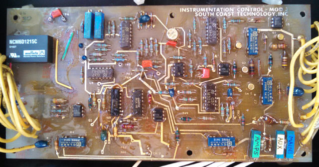
In the end, I selected a Murata power supply from mouser Electronics. It had similar specifications to the one that was originally installed, although it required modifying the printed circuit board a little because the attachment pins were in different locations. Once the instruments and cooling blower were functional again, I found that I needed to calibrate the gauges to agree with the E-meter, which I verified to be accurate. It took some reverse-engineering to figure out which calibration potentiometer was the correct one for each gauge, but once adjusted, I had readings inside the car that I could trust.
Original material ©1996-2025 Mr. Sharkey | All rights reserved