
The Solar System
The Solar System
For the last twenty two years or more, I have been making my own electricity with the use of a home-sized renewable energy system. This system is based around photovoltaic panels, but also includes batteries, inverter and power control circuitry. Two separate systems are used to supply power in differing ways. The following is a description of the systems, with photos where appropriate.
First, the large, grid-intertied system:
PHOTOVOLTAIC PANELS
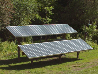
18 Siemens SP75, 36 cell panels, connected in series-parallel to produce 36 volt nominal output. The panels are mounted on a single-axis adjustable frame constructed of pressure treated timbers. The panels are adjustable for elevation seasonally to account for the changing angle of the sun's rays as it moves through the seasons. The panels are racked together with extruded aluminum angle, and fastened into place with stainless steel fasteners.
The nominal power output of these panels on a clear, sunny day is approximately 1000 watts, although peak power on cold, partially cloudy days can top 1500 watts. The power output of the panels is dedicated to a grid intertied inverter. During long, clear summer days I see a production total of 6 kilowatt-hours daily. As of this writing, the system, since it's initial installation in 1998, has produced over 10,200 kilowatt hours of clean, renewable energy, offsetting the use of utility power generated from other less environmentally-benign sources such as large scale hydroelectric (the principle source of electric power in the region where I live).
The output of the solar panels is wired through a combiner which splits the panels into three arrays of six panels each. The individual panels are connected in series strings of three to provide 36 volts, then two series strings of panels are paralleled. The three series/parallel arrays are then sent to the Maximum Power Point charge controller for conversion to 24 volts to charge the battery bank. Normal output current for these panels after being processed by the charge controller is around 36 amperes at 24 volts.
Grounding is important for avoidance of shock hazards and to dissipate lightning, so the PV array and it's associated equipment is connected to a dedicated grounding electrode, and the aluminum frame of the PV racks is also connected to this ground. The equipment is also connected to the utility grounding system through the supply wiring.
BATTERIES
 The system uses four 350 ampere-hour, 6 volt Rolls-Surrette S-460 batteries connected in series. These batteries were recently purchased specifically to allow the system to operate off-grid for extended periods without straining the battery capacity. The local electric utility seems to have outages about once a month in the winter, so the larger capacity is necessary so that the system can be used more effectively to provide backup power for lights, appliances and, importantly, the pump for the pressurized water system on the house. The batteries are enclosed in an insulated, weather-tight enclosure next to the power processing cabinet, and are vented to the atmosphere to allow the dissipation of hydrogen sulfide gas produced during charging.
SHUNTS/WIRING/FUSES
SHUNTS: The system uses standard 50mv shunts, a 500 ampere shunt on the main battery supply connected to the E-Meter and a 50 ampere shunt on the photovoltaic supply connected to a dedicated 0-50 ampere analog meter.
WIRING: Wiring for the system was oversized to allow a comfortable margin for expected currents that would provide the least voltage drop.
The system uses 2-0 welding wire for the batteries and inverter feed, and the PV panels are connected to the combiner with 8 gauge wire. 4 gauge welding wire is used to connect the PV combiner breakers to the charge controller and batteries.
All wiring between the PV modules, and from the modules to the power cabinet is enclosed in code-compliant flexible non-metallic conduits.
DISCONNECT: A 175 amp disconnect is provided to remove power from the 24 volt system for maintenance or fuse replacement.
FUSES: A 150 ampere DC rated fuse protects the 24 volt inverter from overloads, and three 20 ampere DC rated circuit breakers are used for PV panel disconnects. A 60 ampere circuit breaker provides protection and disconnect service to the charge controller. A rack panel of 24 "grasshopper" fuses provides low-current disconnect and over current protection for small loads on this system.
METERING
A variety of meters allow constant supervision of the condition of the solar electric system:
|
|
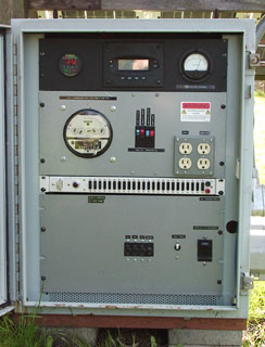
CHARGE SOURCES: A 0-50 ampere, 50mV analog meter displays the output of the charge controller. E-METER: A Cruising Equipment Company digital E-Meter provides continuous information about battery voltage, charge/discharge current, total ampere-hours plus or minus, and total hours until discharged. KILOWATT HOUR METER: A modified utility-type AC kilowatt hour meter is connected in the AC line with the output of the system measure total kilowatt hours produced/delivered to loads. This meter has had a digital counter installed that is capable of counting tenths of a watthour accurately. OUTBACK MATE CONTROL SURFACE/DISPLAY: Both the inverter and charge controller use a dedicated system to display system operation and values, and to allow control and adjustment of the system settings. |
|
|
INVERTER
 |
OUTBACK GTFX2524 :This is a 2500 watt sine wave inverter, and is used primarily to power loads for charge controlling. This inverter will sync up to the power line to allow load diversion and battery charging simultaneously. Multiple digital metering and programming features make this inverter very flexible. Programming and control of this inverter are accomplished by use of the Outback "Mate" display panel and control surface. |
CHARGE CONTROL
|
|
 OUTBACK MX-60: If left unregulated, the current flow from the solar array would overcharge the batteries. To prevent this, an Outback Power Systems MX-60 charge controller which utilizes maximum power point tracking (MPPT) to optimize the amount of power generated by the photovoltaic panels is installed. This charge controller is capable of taking a voltage higher than the battery bank's nominal terminal voltage of 24 volts and stepping the voltage down while increasing the available charging current. The MPPT system integrates the voltage and current being delivered to the battery, calculating the power in watts. The controller then adjusts the operating voltage of the PV arrays to provide the maximum charging current, while continuing to deliver the proper 24 volt nominal charge voltage to the batteries. This is a truly remarkable technology, wringing the maximum available amount of power out of the PV array under all conditions of temperature and light.
POWER CABINET
 The inverter, charge controller, and metering are installed inside a waterproof NEMA style enclosure located underneath the PV array. When I built this system, I decided that I wanted the inverter and batteries as close to the panels as possible. Finding a surplus cabinet that was big enough to hold all of the gear, and completely water tight made it possible to put the important parts of the system right where the power was being generated.
The cabinet has 19" rack rails, which made mounting the various components easy, and allows the system to be changed without having to tear things too far apart, new rack panels can be fabricated and mounted in place of those in the photo if and when the existing equipment is replaced or updated. All of the rack panel equipment is wired using multi-conductor connectors that makes it possible to remove each piece of equipment without altering the wiring. This makes it easy to access the interior of the cabinet for service, in some cases, panels can be removed without even having to power down the cabinet. For instance, the AC rack panel with the kilowatt hour meter and circuit breakers is completely enclosed on the backside so that there is no possibility of shock hazard, and the wiring harnesses have been constructed with adequate length cables to allow the panel to be placed on the ground while the system continues to operate normally. The top panel with the displays can be disconnected and completely removed without affecting the system's operation.
The top panel contains the E-Meter, Outback "Mate" keypad and display, and a 0-50 amp meter for reading PV output current.
Below that is the AC power panel, with a kilowatt-hour meter to accumulate power production totals, circuit breakers for AC power input and output to the inverter, and a pair of convenience receptacles, one on the utility side and one connected to the inverter's output.
The thin panel with the many slots is the "grasshopper" fuse panel, which has only a few fuses installed for the E-Meter and cabinet fans, and a set of binding posts.
The bottom rack panel is dedicated to DC power. Three 20 amp circuit breakers for PV input, a 60 ampere breaker for the MX-60, a 10 ampere breaker to feed the small fuses panel, and a 175 amp breaker for inverter DC input/disconnect.
The inverter and charge controller are bolted to the rear of the cabinet, and the batteries are situated in an external enclosure, surrounded by rigid foam insulation.
12 Volt System
The second photovoltaic system is a stand-alone battery-based system that supplies power for lighting and small appliances in my residence.
PHOTOVOLTAIC PANELS:
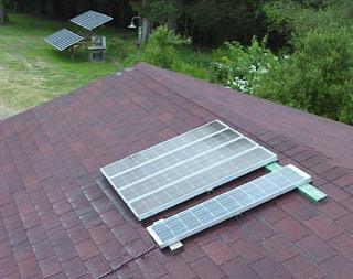
4 Carrizo Solar, 36 cell recycled "quadlam" panels connected in series to provide 12 volt, 4 ampere output. These panels were salvaged from a commercial solar power utility project, then re-sold to the public. (Here's an interesting link to a description and photos of the now defunct Carrizo Solar electric power plant from which these panels were recycled)
1 Siemens M75 48 watt, 33 cell panel, connected in parallel with the 12 volt quadlam panels above.
These panels are installed on top of the carport, and still require some "adjustment" before I'm happy with their presence. For the time being, the aluminum frames that hold the four quadlams and the M75 are simply laid atop 2x4 sleepers set on the roofing material. One good gust of wind from the proper direction and I could have an airborne array.
BATTERIES:
 Storage of the power produced by the 12 volt solar panel array falls to a set of 40 Alcad UHP65, flooded nickel-cadmium batteries. These batteries are 1.2 volts each and series/parallel connected for 12 volts nominal. Total storage capacity is 260 Ampere-hours.
These batteries were all "cast offs" from sources which didn't value them because they did not understand NiCd battery chemistry or how to properly charge or care for them. After topping up the electrolyte and giving each a proper and complete charge, they were revived to full capacity.
SHUNTS/WIRING/FUSES
SHUNTS: A variety of current measuring shunts are employed throughout the system. As some of the recycled meter movements that I chose to use in the 12 volt system did not comply with the default 50mV specification, I manufactured my own homebrew shunts out of various sizes of threaded brass rod, 6-32 rod for 15 amp shunts, 10-32 rod for 30 amp shunts, and 1/4" rod for a 100 amp shunt. A commercial 500 ampere, 50mV shunt is also installed in the system, connected to the E-Meter. The homebrew shunts measure 12 volt PV current, charge current total, and total charge/discharge current of the batteries.
WIRING: As much as possible, wiring for the system was oversized to allow a comfortable margin for expected currents that would provide the least voltage drop. Wiring to the 12 volt batteries is fine-strand 0 gauge, while most small 12 volt loads is 10 gauge. The wiring to the photovoltaic panels is 10 gauge "UF" wire.
FUSES: A variety of overcurrent devices are installed in the system. A 110 ampere Class T fuse is installed in series with a 100 amp DC circuit breaker to protect the Trace 812 inverter on the 12 volt system. Four Airpax low voltage circuit breakers protect the charge sources and loads,. Dozens of automotive-type 3AG fuses protect the metering circuits, which are connected to the shunts in the positive leg of the system (there is a reason for this, but don't make me explain it).
METERING
A variety of meters allow constant supervision of the condition of the solar electric system:
 CHARGE SOURCES: On the 12 volt system, several shunts and associated meters measure incoming charge current from the photovoltaic panels and grid-connected charger on 0-15, and 0-30 ampere analog meter movements.
ANALOG EXPANDED-SCALE VOLTMETER: A homebrew 11-15 volt DC analog voltmeter (constructed from plans found in Home Power Magazine) provides a continuous indication of the battery terminal voltage.
E-METER: A Cruising Equipment Company digital E-Meter provides continuous information
about battery voltage, charge/discharge current, total ampere-hours plus or minus, and total hours until discharged.
AC VOLT METER: For the few times I wish to check the output voltage of the inverters, an antique, copper-cased, iron-vane voltmeter provides the indication on a 0-150 volt scale.
INVERTER
Inverters convert the direct current from the batteries to 120 volt alternating current:
 TRACE 812: The workhorse inverter in this system is a little Trace Engineering 812, a 600 watt modified sine-wave inverter. This power conversion device runs all of my AC lighting (compact fluorescents and low-wattage incandescent), kitchen appliances, stereo equipment and more. In the early days of the system, it even runs the hair dryer, Skil saw, belt sander and various shop tools. This inverter will surge to 1200 watts for a short period, and so far, it has been indestructible.
It includes a 25 ampere battery charger that can replenish battery usage from utility power. Most of the year, I receive sufficient power from the solar panels to keep the batteries charged on a daily basis, but during the shortest days of winter, with frequent cloud cover, it is necessary to charge from grid power. Keeping the batteries topped up is not only good for their health, but since I rely on this system for powering lighting and appliances such as the telephone answering machine, it's important to have a full charge in case of utility power failure. As such, I will frequently charge the batteries from grid power when it looks like the utility power may fail, usually during the frequent wind storms that we experience in the winter here.
CHARGE CONTROL
If left unregulated, the current flow from the solar array would overcharge the batteries. To prevent this, a Trace C-12 charge controller limits the terminal voltage to the batteries in three steps, bulk, absorption and float. It also has provisions for battery equalization and has an LED indicator showing what mode of operation it is in. The controller has a temperature sensor so that battery voltage can be compensated due to temperature variances.
NANO HYDRO POWER
 Domestic water at my home is supplied by spring water, collected high on a hillside above the house. There is pressure in the pipe even when I am not using water, so I built a junk box parts hydroelectric generator to utilize the potential power. A tiny plastic Pelton wheel is coupled to a small permanent magnet DC motor, which acts as a generator when the shaft is rotated. The penstock (water line from the spring) is only ¾" in diameter, which limits the useful amount of power to 11 watts. This doesn't sound like very much, but over the course of 24 hours, it's enough to power my cordless phone and answering machine, caller ID reader, and provide lighting to my desk and kitchen, even through the dark months of winter. This complements the power from the 12 volt photovoltaic system very nicely.
A planned upgrade to the system to use larger pipe would allow harvesting a much greater amount of power, as the spring source frequently has a hundred gallons per minute or more flowing in the winter months, when power is most valuable. Of course, the small generator would need to be replaced with a larger, alternator-based generator, but such devices are available.
More information on this small hydro generator is available in this blog post.
In addition to equipment actually installed and related to the two photovoltaic systems, I have several other pieces of gear that see occasional use or that help me keep tabs on the climate and weather conditions:
INVERTERS
HEART 1200: While not actually installed in my system, I have a salvaged Heart Interface 1200 watt modified sine-wave inverter hanging around in case I need portable power on the tractor or on a job. This inverter was purchased from a local RV manufacturer as scrap and refurbished to operating condition.
POWERSTAR POCKET SOCKET: Also not part of the solar system proper, I keep this 100 watt inverter in the pickup in case I need to solder something, or run the compact fluorescent trouble light. It has on one occasion kept an FM radio station translator on the air during a power failure.
WIND GENERATORS
 Not installed, but I have two. The first, a vintage Winco Winpower which has been completely restored and converted to 12 volts. This machine was manufactured in the 1920's and 30's and was a standard fixture on rural farms to charge batteries for powering the latest craze, radio listening. Although it is fully functional, and will swing into motion with the slightest breeze, I was never comfortable allowing it to be exposed to the winter weather, and would only install it for a few months over the summer as a mobile sculpture.
The second machine is a Southwest Windpower AIR 403, which I purchased to replace the Winco. Made of modern materials and being completely waterproof, it was left installed year-round. Of course, in order to get an adequate supply of wind, it's necessary to have a sizeable tower to mount the machine atop, but I never wanted to incur the wrath of the building permits department in the city offices, so a short stub tower of 22 feet was used. No real usable power ever came out of either of my wind plants as a result.
These days, it makes more sense in the location in which I live to develop small-scale hydro power, as there are multiple springs on a tall hillside to the north end of my property. After what could be a difficult installation of delivery piping, I could run heat all day and all night in the winter from the available flow of falling water and never see the electric bill increase one bit.
WEATHER STATION:
While not strictly an instrument connected with the solar electric power system, a Weather Measure anemometer and wind direction combination provides direct measurement of the wind velocity on two large analog meters mounted in my living room. This weather station appears to be instrument grade, and was originally purchased by the county air pollution control authority to monitor weather conditions at a radio station. It is powered directly by 12 volts DC, so it is operable during power failures.
FLAT PLATE SOLAR WATER HEATER
 As I do not live on property which has geothermal possibilities, I had to come up with a renewable energy solution to heating water for the hot tub. After using a home-built collector for some years, I was given a commercially manufactured flat plate collector with an area of 4 by 8 feet. This collector is equipped with all of the proper accessories, low-iron glass, anodized aluminum collector plates, and an extruded, gasketed, sealed enclosure. The difference in heating efficiency between the home built collector and the manufactured one is astounding! I have a total of three of these 4x8 collectors. Once the other two are online and operating, I should have more than enough hot water to run the washing machine, showers and all of my domestic hot water needs from solar.
A small AC powered centrifugal pump circulates the water from the tub through the flat plate collector, and a Goldline SP-30 electronic setpoint controller senses collector temperature and controls the pump accordingly.
SOLAR POWER IN THE DAYS OF YESTER
In summer of 2005, nearly the entire system was rebuilt and re-outfitted with new equipment. Some of the solar power equipment I had used up until this time was borrowed seasonally from the Oregon Country Fair. My association with this group ended formally in 2005, and I returned the equipment for the last time in June of that year. This allowed me to make choices of newer, more appropriate equipment to better serve my needs.
In fall of 2006, I moved away from the urban rat race to a small community in the central Coast Range of Oregon. My 24 volt solar power system was in storage for eight months before I could find the time to reinstall it and get the power flowing the correct direction again. With the reinstallation, I took the time to build a more robust framework to mount the panels on, and invested additional time in the grounding of the system. The new site has much better access to sun in the winter months, so I am experiencing improved performance compared to the former site, which was limited in the amount of clear sky available.
Original material ©1996-2025 Mr. Sharkey | All rights reserved