
LPG Fumigation - Page Three
LPG Fumigation
Page Three
Control Systems:
For any installed LPG system, you will need at least a basic electrical control system to activate the solenoid valve, as well as protection and interlocking circuits to make sure that the propane is turned off when the engine is not running. Here's a description of how my system is wired:
-
First and most important, the 12 volt power to run the solenoid valve is supplied from the switched side of the ignition system. This insures that the gas is always off when the ignition switch is off. The supply wiring to the rest of the circuit is protected by a fuse.
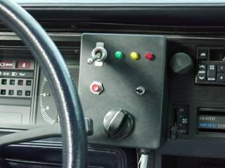
In this photo, the LPG switch is mounted in a plastic box along with the other Pusher
controls, but you could just as easily put it in a hole drilled into the dash. -
On/Off switch on the dashboard. On my system, I use the gas for a boost during passing and hill climbing mostly, so I need to be able to control the LPG "on the fly". It's a good idea to have one on any system, so that you can defeat the gas when the engine is cold, or in case a problem requires shutting down the gas.
-
A throttle-mounted switch to prevent gas from entering the engine during idle conditions. You don't need additional power while sitting stopped at a signal, and from experience, I can tell you that you probably won't remember to shut it off manually. Adding gas during idle will also result in a fast idle, which isn't necessary either.
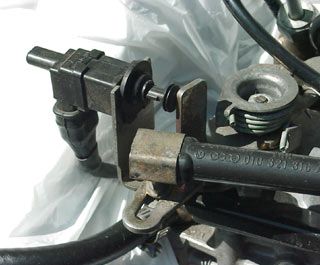
I lucked out and the injection pump for the Pusher already had a switch mounted,
although I did easily fabricate one for my other BioDiesel Rabbit. -
An interlock that prevents gas from entering the engine when it isn't running. "Oh, isn't that the ignition switch"? you ask. No, it's not. What happens if the engine dies, or you turn on the ignition to listen to the radio, or you're having trouble getting it started and are holding the throttle open while your crank it, or any of 19 other "impossible" scenarios that can dump gas into the motor while it's not running and consuming the fuel? Forget it, install an interlock tied to the engine oil pressure and you're done. No oil pressure means that the engine isn't running (or won't be for very long) and the gas should stay off.
There are two ways to sense oil pressure. One way is to install a "Hobbs switch", which is a normally-open contact device that closes the circuit and supplies power to the gas solenoid when it senses oil pressure in the engine. This type of switch must be installed on the engine oil gallery, either by using a "T" fitting, or by attaching it to a spare oil port on the engine, if one exists.
The other method, which I used, is to use the existing oil pressure "idiot light" switch to supply logic to the interlock circuit. Unfortunately, oil pressure indicator lights are the exact opposite logic from what is needed, so an interface circuit is needed to turn the normally-closed oil pressure switch into a normally-open one. This simple circuit monitors the indicator logic and simply reverses it for the interlock without affecting the operation of the oil pressure indicator on the instrument panel of the car:
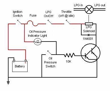
The Darlington transistor should be a power type and be properly
heat-sunk. If you use a Hobbs switch, put it in place of the
Darlington transistor, on the negative side of the LPG solenoid,
and ignore the connection to the oil pressure indicator light. -
[Optional for turbo engines] Many installations on turbocharged engines utilize a pressure switch on the intake manifold that detects boost pressure and turns on the gas when the pressure reaches a preset level. Generally, this level corresponds to increased load on the engine encountered during passing or hill climbing. The "Hobbs" switch described above would be one choice to control the solenoid.
Multiple-Stage Control:
An additional thought would be to use multiple pressure switches connected to multiple solenoid valves, each with it's own orifice supplying gas to the engine. In this manner, the quantity of gas could be increased as boost pressure increases, giving an approximation of commercial systems that use a boost-adjusted regulator. My vision might be for a three solenoid system, with three differing orifices. By building a controller that integrates boost pressure switch operation to allow any single or combination of solenoids to be open depending on boost pressure at the time, seven levels of gas quantity could be supplied, which should be enough to give good overall tracking response.
| Boost Pressure | Solenoid valve(s) open | Orifice Size | Gas flow |
| 0 PSI | None | --- | Zero |
| 2 PSI | #1 | small | x1 |
| 4 PSI | #2 | medium | x2 |
| 6 PSI | #3 | large | x3 |
| 8 PSI | #1 & #2 | small + medium | x4 |
| 10 PSI | #1 & #3 | small + large | x5 |
| 12 PSI | #2 & #3 | medium + large | x6 |
| 14 PSI and above | #1 & #2 & #3 | small + medium + large | x7 |
Of course the boost pressures cited in this table are only an example. With experimentation it might be possible to adjust pressure switch settings to utilize a wider range of pressures, or to be non-linear in response, for example to be optimized for boost pressures encountered normally when the vehicles is cruising at freeway speeds, or to allow more accurate quantities of gas to be delivered under heavy loads, etc. Such a system would have many variables, but would also allow the greatest amount of "tuning" to be undertaken. Addition of a fourth solenoid and orifice would make the system more complex, but introduce even greater control of the quantity of gas delivered.
Commercial Variable-Rate Systems:
The commercially available systems which I have knowledge of use a controller to determine the rate of gas necessary, sending control signals to variable valves which meter the gas to be sent into the engine. They are of several types, the most common being stepper motor valves, and needle valves.
Stepper motor systems work fairly well, but due to the delay in the reaction of the motor to the control signal, they tend to lag a bit in response. This can mean lack of power when it's needed, and worse, too much gas at the wrong times as the valve closes slowly in response to the controller.
Needle valve systems have nearly instant reaction times to control signals, but of course, the increased performance comes at a monetary price.
Any sophisticated LPG system would by necessity tap into the engine management computer to sense EGT, load, RPM, and critical engine conditions. Properly integrated LKPG control systems would have software written to read and react to the engine management computer, or even replace it in extreme installations.
Up Next: Figuring it Out
Original material ©1996-2025 Mr. Sharkey | All rights reserved