
Taming Lester 6
This project moves forward, however slowly. Actually, given that I have numerous other things that are much more important, that it is getting an attention at all is surprising. With Fall approaching, I should be spending all my time getting roofs repaired, the walls put up on my storage building, and some firewood cut, split and stacked.
The charger does have some priority, as the full-time project for the radio station that I've been anticipating for the last six months may actually be getting under way within a week or two, and I'll need to drive into town nearly every day until it's completed, Using the EV to rack up those miles will be a real fuel budget saver. Being able to charge up the EV at a fast rate will be important if I expect to be able to use it as daily transport.
Yesterday, I finished the wiring on the chassis, installing the AC input wiring and DC output cable. The AC wiring is a good length of 8/4 SO cable, #8 gauge, four conductors (two hots, a neutral and ground) sheathed in tough rubber. The cord cap is a 250 volt, 50 ampere, two-pole with a ground.
The DC cable is about ten feet of #8 twisted pair, a gift from TMAX from his stash of old Telco wiring salvaged from the dumpster behind LA7. I installed the 50 ampere Anderson connector that mates with the EV's battery pack on the far end. These cables will do the job for now, If this charger gets a lot of use, I might replace the twisted pair cable with some more supple auto jumper cable wire, which is probably a bit better protected in an exposed application.
Finishing the chassis wiring required me to complete the make-over of the front panel of the charger, as several switches, circuit breakers, and pilot ights, etc. needed to be installed for the wiring to be soldered in place internally. Here's a pic of the old front. There were multiple cartridge fuses for apparatus that no longer existed, large gaping holes for cables that were lost long ago, and a socket for a "watthour counter" that incremented a mechanical counter on the dash of the EV. All of that's gone now.

To correct the panels appearance and function, I needed to replace the panel entirely, or at least cover it so I could lay out my components in an orderly manner according to my own design. Scratching around in the woods where I store leftovers from the bus building yielded some aluminum sheet, whcih I grafted to the front.
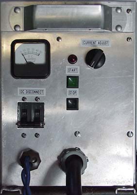
The only things I retained were the ammeter and the "overtemp" light, which will be a simple power indicator now. The original "push to start" and "reset" push buttons were of questionable quality, so I dug through the junk box of switches and found some better replacements, using them as "Start" and "Stop", controlling the AC contactor in the charger. The DC Disconnect is a pair of 100 ampere circuit breakers. I used two, one each in the positive and negative DC legs because the breakers are rated at 95 volts DC, and the EV battery pack tops out at 130 volts DC. I wanted to be sure I could shut off the feed to the batteries without any sustained arcing. The DC Disconnect breakers have an internal microswitch for alarm control. In this application, I used this switch in series with the contactor control circuit. The DC breakers must be in the "on" position to turn on the charger's AC power, and if there is any fault in the DC side of the charger that causes the breakers to trip, the AC side of the charger is de-energized as well. Fail safe!
The "Current Adjust" control will be connected to the phase control circuit that I've prototyped, but now need to permanently build on a perf board. It may seem to be crowding the pilot light, but in the next stage of construction, I'll add a voltage control to the front panel, and it will be mounted to the right of the current control.
Original material ©1996-2025 Mr. Sharkey | All rights reserved