
Taming Lester
Now that I've gotten the EV Rabbit back on the road, I have some charging issues to address. The on-board charger on the car is a K&W BC-20, which is small, light, and powered by a normal 15 ampere 120 volt wall receptacle. While this is convenient for opportunity charging, and works fine when I am at home and have a lot of time to charge, the current output of the K&W leaves something to be desired when filling up the batteries fast is required. The K&W is rated at 20 amperes, but it will only do this from a solid 20 or 30 ampere circuit, then then only for a few minutes until it heats up and cuts back power to keep from cooking itself. Most of the time, I see 17 amps of line current, meaning about 14-15 amps into the batteries. I usually have to cut back on the power when charging from 15 and 20 ampere outlets to keep from overheating the cord and plug ends. Even the higher power outlet that I tacked into the radio station's sub panel restricted the charging current to about 10 amperes into the battery, meaning that I had to wait around for three hours to fill the batteries before heading home.
What I really need is a way to hammer ampere-hours back into the batteries at a high rate, preferably from a 240 volt source to keep the line losses and voltage drop to a minimum.
From the factory, the car came equipped with a Lester "Lestronic" charger, an old-tech, transformer-based monster that weighed in over a hundred pounds, and sometimes even worked. Here's the manual on mine, in case you want details. This charger operates from 240 volts, and the voltage-regulated output is 32 amperes of charge current. The biggest problems with these chargers are that they are big, heavy, and in my case, broken. I did receive the original charger when I bought the car, even though it already had the K&W installed. The Lester was mostly complete, but was missing some circuit boards, and the power relay.
Last week, I dug the charger out of the storage locker to have a look at it to see if there were any salvageable parts. My intention was to maybe get it running and leave it at the radio station for fast-charging the car on trips to town. As it was, it was not useable, but the transformer is still good, and the SCR rectifiers operable. Time for a new project.
I stripped it down to a bare chassis, just the transformer, the SCR's and the fuse block. After that, used the high pressure washer to blast the chassis and transformer clean of accumlated dirt. A few minutes of compressed air hose-down followed by hours sitting in the full sun dried the components. Then I used my Variac to apply voltage to the input side of the transformer to see if it was OK. To preclude fireworks, I did all my testing at 24 volts of input, 1/10 normal. I looked for 1/10 normal output from the transformer, and also checked several additional secondaries on the transformer for voltage levels.
Next, I tried firing the SCR rectifiers, using a diode between the gate and anode terminals. The result was DC output at approximately 12 volts (1/10 normal output).
Here's a shot of my test setup. The 'scope shows a perfect rectified full wave signal, and there's a 25 watt, 12 volt lamp under the funnel to the left of the frame as a load (the funnel is used as a shade, I was tired of seeing spots):
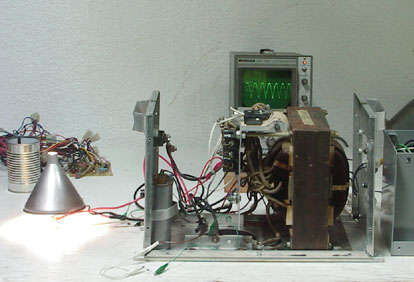
In the background on the left is a tangle of wiring and connectors that I removed from the chassis. I'm starting with a bare bones chassis and working my way up from there.
When the Lester was designed and built, the control circuitry was designed around discrete components, because that was about all that was available at the time. These days, there are integrated circuits that can replace all of the circuits in the original controls, and will provide more features and better control of the voltage and current.
For instance, to control the SCR rectifiers, I'm looking at using the TCA785 phase control IC. This is a one-chip solution to a whole PC board full of discrete components in the Lester, and will give much tighter timing of the thyristors than the original.
That's the start. Next I'll try raising the input voltage (slowly and carefully) to 120, and then 240 volts, using a high-wattage light bulb as a load. If that doesn't produce smoke, I'll try connecting to the EV's batteries and see if I can produce some brute-force charging. Once the phase control chips come in, I can try some voltage and current regulation, and start assembling some protection circuitry.
Original material ©1996-2026 Mr. Sharkey | All rights reserved